A Guide to Acousto-Optic Driver Operation and Key Specifications
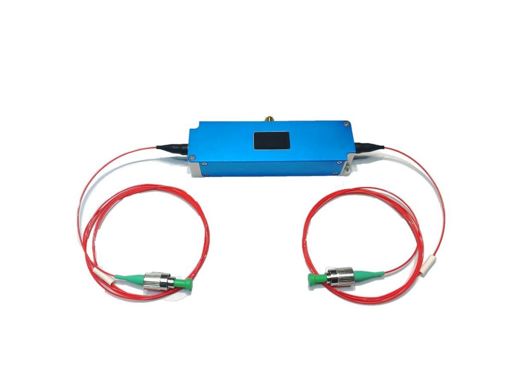
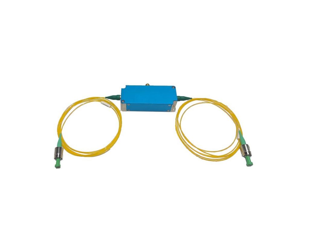
Light is used in a variety of technologies, including optical communications and laser processing. Acousto-optic modulators are essential components for manipulating light beams in a variety of applications. However, to fully realize their potential, we require a conductor known as the acousto-optic driver. As a professional acousto-optic modulator driver supplier, Smart gives you the inner workings of acousto optic drivers, explaining how they convert electrical signals into precise control of light beams. We’ll then go over the key specifications that define an acousto optic driver’s performance and guide the selection process for your specific requirements.
How Does an Acousto Optic Driver Work?
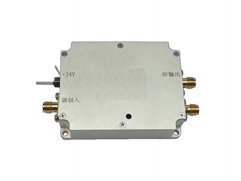
An acousto-optic modulator driver controls an acousto-optic modulator. Here’s a detailed breakdown of how it operates:
1. Input Signal
The acousto optic driver receives an input signal indicating the desired manipulation of the light beam. The signal can be:
- Analog: Representing a continuously varying voltage that controls the intensity of the light beam.
- Digital: A binary signal (often TTL) indicating on (high voltage) or off (low voltage) states for the light beam.
- Pulse: A short electrical pulse used to generate brief bursts of light.
2. Signal Processing and Amplification
The acousto optic driver’s internal circuitry processes the input signal. This may entail filtering, shaping, and amplification to ensure compatibility with the acousto-optic modulator’s needs.
- Filtering: Removes unwanted noise from the input signal to maintain a clean output.
- Shaping: May adjust the signal’s rise time (speed of transition between on and off states) for optimal performance in pulsed applications.
- Amplification: Boosts the signal strength to a level sufficient for driving the piezoelectric transducer within the acousto-optic modulator.
3. Radio Frequency (RF) Signal Generation
The processed signal is then converted to radio frequency (RF) signals. This conversion usually involves:
- Voltage-Controlled Oscillator (VCO): In response to the input signal, the VCO generates an RF signal with a frequency directly proportional to the input voltage (for analog signals) or a specific pre-set frequency (for digital or pulsed signals).
- Wave Shaper: May further refine the RF signal’s shape to ensure it efficiently excites the piezoelectric transducer.
4. Driving the Piezoelectric Transducer
The generated RF signal is sent to the acousto optic driver’s final output stage, which includes a power amplifier. This amplifier boosts the RF signal to a level where it can effectively drive the piezoelectric transducer inside the acousto-optic modulator.
- Piezoelectric Transducer: This component converts the amplified RF signal back into a physical vibration (sound wave) with the appropriate frequency. The sound wave travels throughout the acousto-optic modulator’s material.
5. Acousto-Optic Effect in the Acousto-optic Modulator
Inside the acousto-optic modulator, the sound wave causes a periodic variation in the material’s refractive index. This variation functions as a diffraction grating for the incoming light beam.
- Bragg Diffraction: Light interacts with the grating caused by the sound wave. Depending on the conditions, some of the light is diffracted in a new direction, while the remainder passes through the acousto-optic modulator.
6. Light Beam Modulation
Controlling the RF signal from the acousto optic driver allows us to manipulate the sound wave and, consequently, the light beam.
- Analog Modulation: Changing the input signal voltage to the acousto optic driver alters the RF frequency, which changes the intensity of the diffracted light beam, resulting in analog control.
- Digital Modulation: Turning the input signal on and off generates or eliminates the sound wave, resulting in a fully diffracted or transmitted light beam, allowing for digital on/off control.
- Pulse Modulation: Short electrical pulses from the acousto optic driver cause brief bursts of sound waves, which result in short light pulses.
In conclusion, the acousto optic driver serves as a translator between the electrical control signal and the sound wave in the acousto-optic modulator. The acousto optic driver generates the appropriate RF signal to precisely control the behavior of the light beam after careful processing and amplifying the input signal.
What Are Some Key Acousto Optic Driver Specifications?
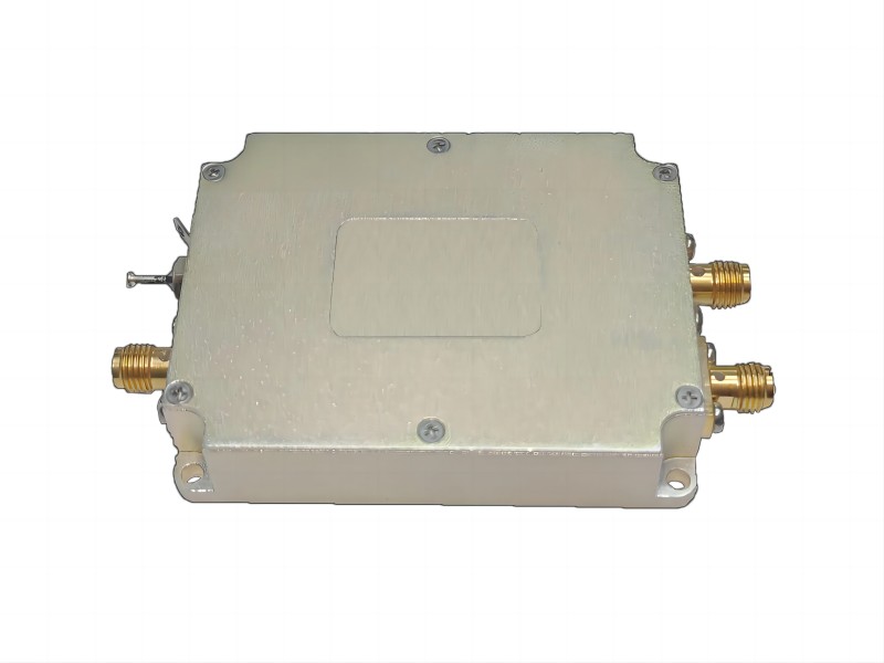
Acousto-optic drivers are critical components in many optical systems, allowing for precise control of light beams. Selecting the appropriate acousto optic driver necessitates careful consideration of its specifications, which define its performance and suitability for specific applications. Here is a detailed table summarizing key acousto optic driver specifications:
| Specification | Description | Importance |
| Operating Frequency (RF Range) | Range of radio frequencies the acousto optic driver can output (e.g., 40 MHz to 200 MHz). | Determines the compatibility with the acousto-optic modulator’s acoustic resonance frequency and the desired modulation bandwidth. |
| Output Power | Electrical power the acousto optic driver can deliver to drive the piezoelectric transducer (e.g., 1 watt). | Influences the intensity of the sound wave generated within the acousto-optic modulator, affecting diffraction efficiency and modulation depth. |
| Modulation Type | Method of controlling the light beam: analog, digital, or pulse. | Determines the nature of light beam manipulation: continuous intensity variation (analog), on/off switching (digital), or generation of light pulses (pulse). |
| Rise Time | Time it takes for the light beam intensity to transition between on and off states (important for pulsed modulation). | Affects the pulse duration and sharpness, crucial for applications like laser ranging and Q-switching. |
| Input Impedance | Electrical impedance of the acousto optic driver’s input terminals. | Ensures proper signal matching between the acousto optic driver and the external signal source to minimize reflections and power loss. |
| Output Impedance | Electrical impedance of the acousto optic driver’s output terminals. | Ensures efficient power transfer from the acousto optic driver to the piezoelectric transducer within the acousto-optic modulator. |
| Power Supply | Voltage and current requirements for the acousto optic driver’s operation. | Determines the power source needed to drive the acousto optic driver’s internal circuitry and provide sufficient output power. |
| Operating Temperature Range | Range of ambient temperatures within which the acousto optic driver can function reliably. | Ensures proper operation in the intended environment, considering potential thermal fluctuations. |
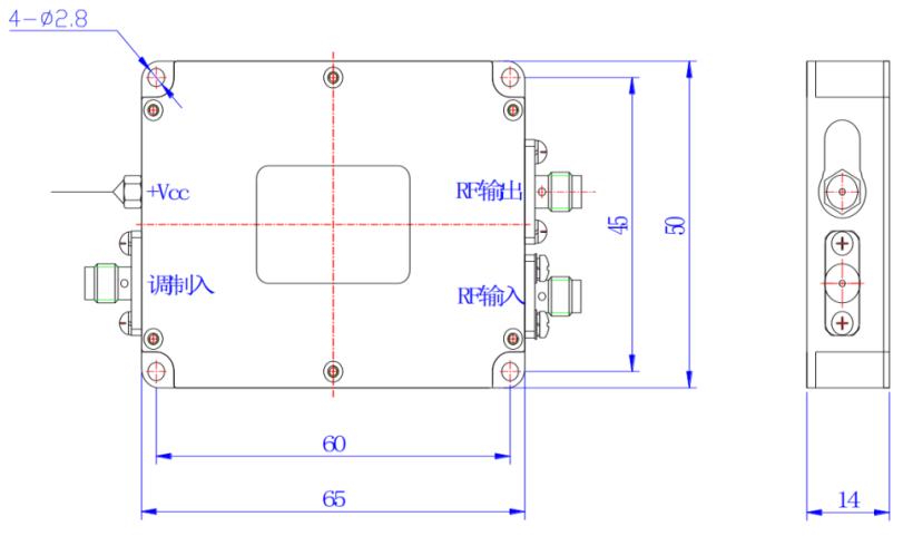
| Package Dimensions | Physical size and mounting options of the acousto optic driver. | Allows for integration into the optical system with adequate space and mounting compatibility. |
By carefully evaluating these specifications and other factors, you can choose the acousto optic driver that best meets the needs of your particular application, ensuring optimal performance and system compatibility.
Conclusion
Understanding the intricate operation of acousto optic drivers and their key specifications provides you with the knowledge needed to maximize their potential in your optical systems. Acousto optic drivers provide a powerful tool for manipulating light, ranging from controlling light intensity to generating precise light pulses. By carefully considering the operating frequency, output power, modulation type, and other critical specifications, you can select an acousto optic driver that seamlessly integrates with your acousto-optic modulator and provides optimal light beam control for your application. Whether you’re creating a laser communication system, a material processing setup, or another light-based technology, acousto optic drivers act as silent conductors, orchestrating the flow of light with remarkable precision. And we have published another article: Choosing the Right Acousto-Optic Modulator Drivers. Maybe you are also interested in it.

