Electric ODLs: Enabling Precise Time Control in Optical Systems
Electric Optical Delay Lines (EODLs) have emerged as crucial components in modern optical systems, offering precise and dynamic control over the temporal characteristics of optical signals.
This article provides a comprehensive overview of EODLs, encompassing their fundamental working principles, diverse applications, and key performance parameters. We will delve into the mechanisms by which EODLs manipulate optical signals, explore their critical role in various fields such as optical interferometry, fiber optic sensing, and terahertz time-domain spectroscopy, and analyze key performance metrics including delay precision, delay range, and insertion loss.
Furthermore, we will examine real-world application examples, showcasing how EODLs are integrated with other optical components to achieve groundbreaking results in scientific research and technological advancements.
Working Principle of Electric ODL
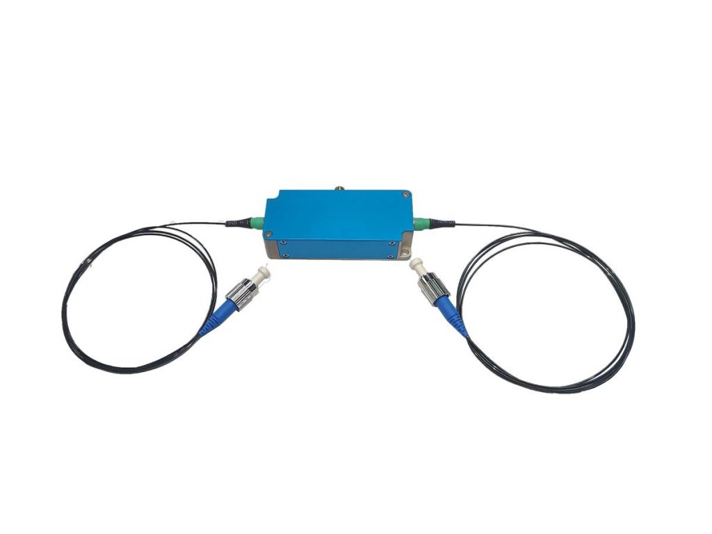
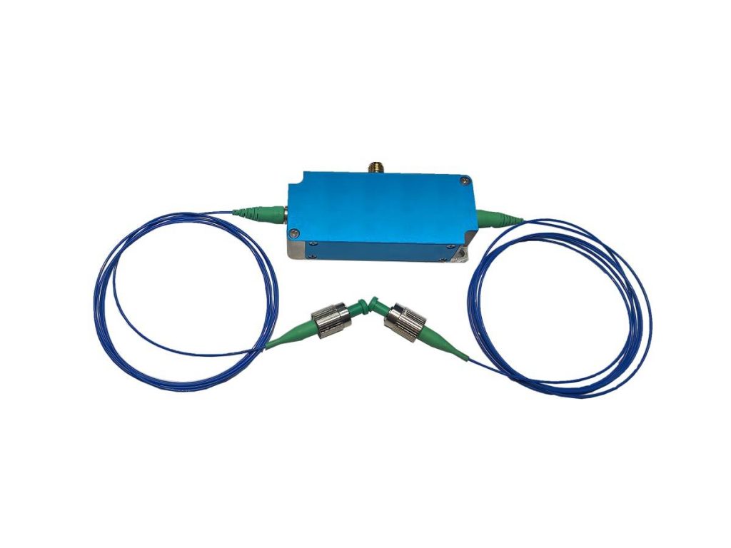
Electro-optic delay lines (EODLs) utilize the electro-optic effect to induce a variable delay in optical signals by altering the refractive index of a material via an applied electric field.
Comparison with other optical delay techniques: Compared to other optical delay technologies, EODLs offer unique advantages such as high precision, wide delay range, and fast tuning speed, making them suitable for various applications demanding precise temporal control of optical signals. However, factors such as insertion loss and cost should also be considered for specific applications.
Applications of Electric ODL
In Optical Interferometry
Optical interferometers are crucial instruments for precision optical measurements. Electric Optical Delay Lines (EODLs) can introduce precise time delays, enabling precise control and measurement of optical path differences. One might wonder how EODLs interact with other components in an optical interferometer and how they enhance performance metrics such as measurement accuracy and resolution. For instance, in a Michelson interferometer, an EODL can be used to fine-tune the path length difference between the two arms, providing a more precise measurement of the phase difference between the interfering beams. This can be particularly useful in applications such as displacement measurement, surface profiling, and refractive index measurement.
In Fiber Optic Sensors
Fiber optic sensors find wide applications in various fields. EODLs can be used to delay optical signals within fiber optic sensors, enabling high-precision measurement of physical quantities like temperature, pressure, and strain. Specific interest lies in understanding how EODLs are implemented in different types of fiber optic sensors and how optimizing delay line parameters can improve sensor performance. For example, in a fiber Bragg grating (FBG) sensor, an EODL can be used to demodulate the wavelength shift of the reflected Bragg wavelength, providing a more accurate measurement of the applied strain.
In Terahertz Time-Domain Spectroscopy
Terahertz time-domain spectroscopy (THz-TDS) is an emerging spectroscopic technique. EODLs can be used to achieve precise time delays between the probe and pump pulses, improving the measurement accuracy and signal-to-noise ratio of THz signals. One might want to understand the specific workflow and parameter requirements of EODLs in THz-TDS systems, and how they influence the results of THz spectral analysis. For instance, in a THz-TDS system, an EODL can be used to precisely control the time delay between the THz pulse and the optical gate pulse, allowing for accurate measurement of the THz waveform and subsequent Fourier transform to obtain the THz spectrum.
Performance Parameters of Electric ODL
Delay Precision
This is a critical performance metric for Electric Optical Delay Lines (EODLs). One might wonder what the minimum delay resolution achievable by an EODL is, and what factors influence delay precision, such as the accuracy of electric field control, the transmission characteristics of the fiber, and environmental factors. Additionally, methods for measuring and calibrating delay precision would be of interest. For instance, the precision of an EODL is often limited by factors such as the stability of the applied voltage, the uniformity of the electro-optic crystal, and the thermal expansion of the optical components. To improve delay precision, techniques like temperature stabilization, active feedback control, and calibration using a frequency comb can be employed.
Delay Range
The delay range refers to the maximum optical path delay that an EODL can provide. There is interest in the specific numerical value of the delay range and how to select an EODL with a suitable delay range for specific applications. Additionally, the relationship between delay range and delay precision, as well as methods to extend the delay range while maintaining a certain level of precision, are of concern. For example, the delay range of an EODL can be increased by using longer interaction lengths or stronger electro-optic effects. However, increasing the delay range may also lead to a decrease in precision due to factors such as increased dispersion and nonlinear effects.
Insertion Loss
Insertion loss reflects the attenuation of laser power in the delay line system. One might wonder what the typical insertion loss of an EODL is and how to reduce insertion loss to improve the transmission efficiency of the optical signal and the accuracy of measurements. Factors contributing to insertion loss include Fresnel reflections at optical interfaces, absorption in the electro-optic crystal, and scattering losses in the optical fiber. To minimize insertion loss, anti-reflection coatings can be applied to optical surfaces, and low-loss optical fibers can be used. Additionally, optimization of the coupling efficiency between the optical fiber and the electro-optic crystal can also help to reduce insertion loss.
Real-world Application Examples of Electric ODL
Specific Measurement Tasks
People may be interested in real-world examples of how Electric Optical Delay Lines (EODLs) are used in specific optical measurement tasks, such as high-precision optical length measurement, optical thin film thickness measurement, and optical properties measurement of biological tissues. This includes understanding the measurement principles, methods, and procedures, as well as the final measurement results and accuracy, in order to gain inspiration and learn from these examples. For instance, in high-precision optical length measurement, an EODL can be used in a Michelson interferometer to introduce a precisely controlled optical path difference, allowing for highly accurate determination of the length of an object.
Integration with Other Equipment and Techniques
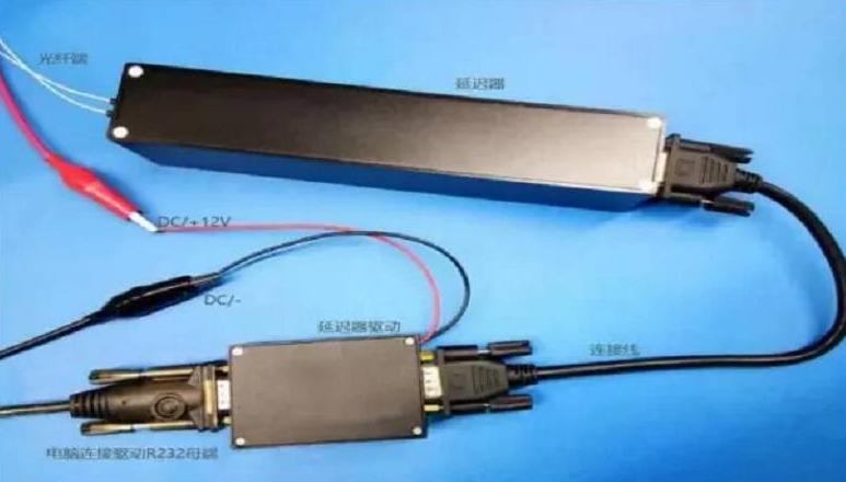
EODLs are often used in conjunction with other optical equipment and techniques, such as lasers, detectors, and signal processing systems. People may be curious about the interfaces and compatibility issues between EODLs and other devices in these combined applications, as well as how to integrate and optimize the system for optimal measurement results. For example, in a time-resolved fluorescence spectroscopy system, an EODL can be used to introduce a variable delay between the excitation pulse and the detection window, allowing for the measurement of fluorescence lifetimes. The integration of the EODL with the laser, detector, and signal processing electronics requires careful consideration of factors such as timing synchronization, signal amplitude, and noise.
Key Takeaways
Smart Sci & Tech has introduced the electric optical delay lines have proven to be invaluable tools in modern optics, enabling precise control over the temporal characteristics of optical signals with numerous applications across various scientific and technological domains. Their ability to introduce precise and dynamically adjustable time delays has revolutionized fields such as optical interferometry, fiber optic sensing, and terahertz time-domain spectroscopy.