How to Choose the Right Acousto-optic Modulator Driver?
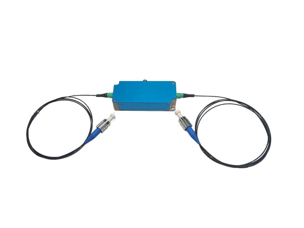
An acousto-optic driver designed to provide radio frequency electrical signals for AOM. There are four types of drivers (regular types) to choose from: frequency shift only drivers, digital modulation drivers, analog modulation drivers, and RF signal amplifiers. So how should we choose the appropriate drive?
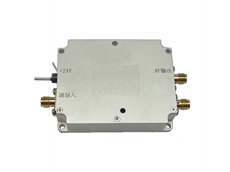
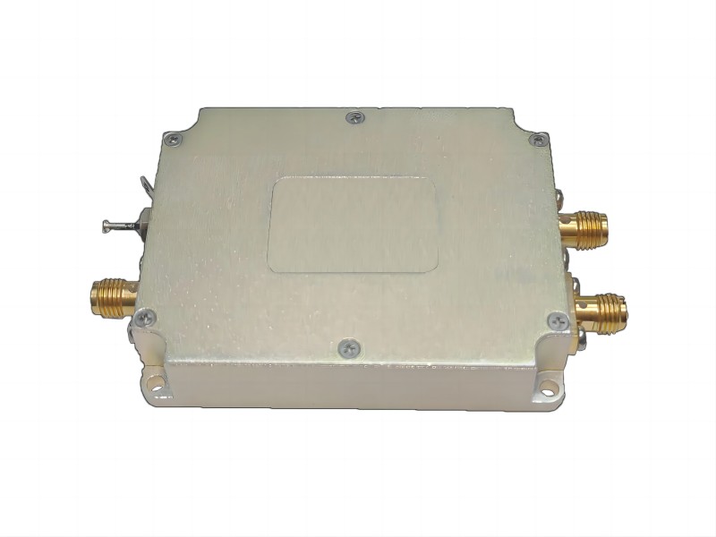
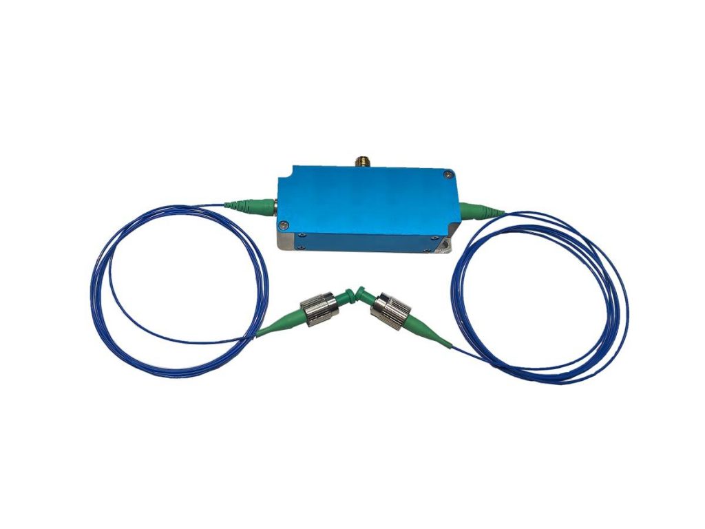
Frequency shift only driver, suitable for systems with only frequency shift requirements. When used in conjunction with AOM, the input light frequency can be positively or negatively shifted, and the frequency shift amount can be determined according to the demand. These types of drives only require a power supply (24V or 12V) to function properly. As shown in the figure:

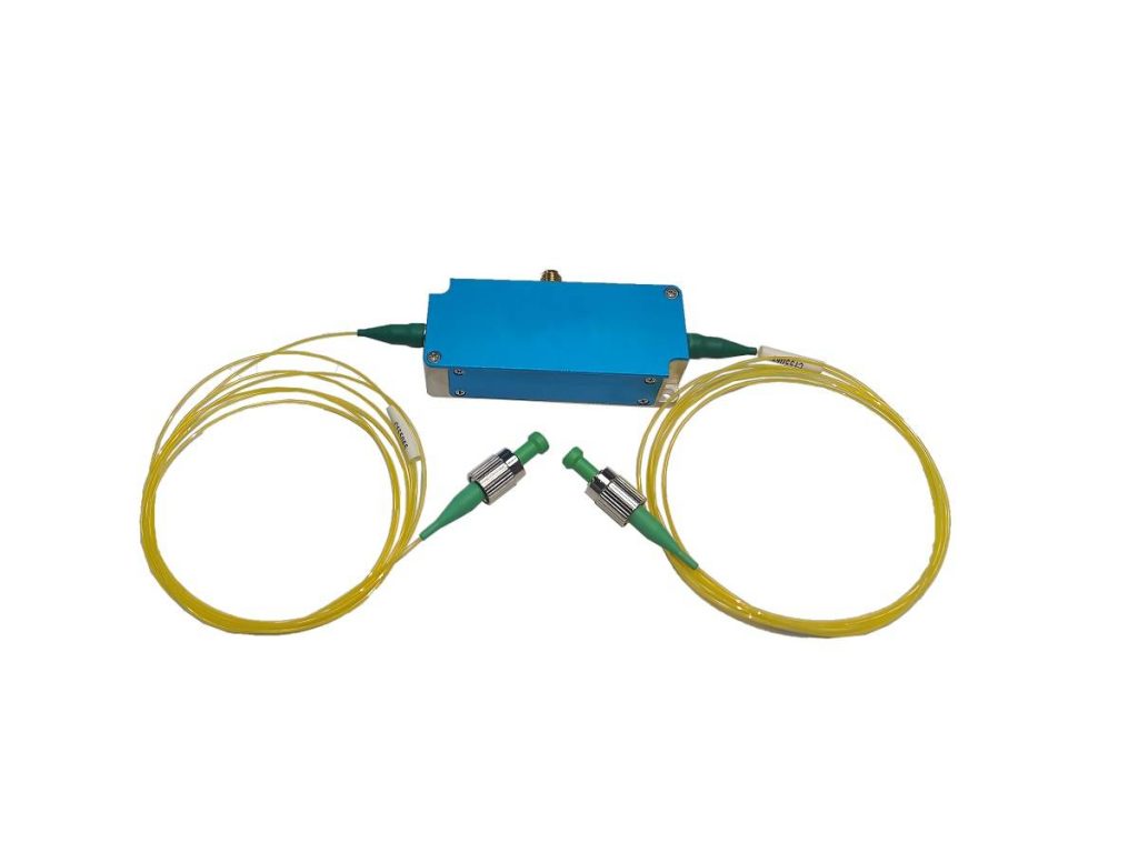
A digital modulation driver, suitable for systems that require digital modulation of optical signals, is usually used for optical switches. This type of driver not only requires a power supply (24V or 12V), but also inputs digital signals for modulation. The digital signal requires a TTL level: high level 3.3-5V, low level 0-0.2V@1k Ω. The frequency range of digital modulation signals may vary depending on different models. As shown in the figure:

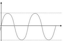
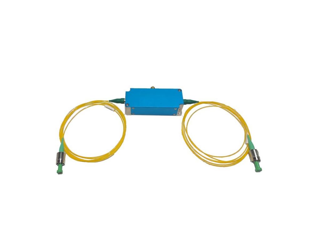
Analog modulation driver, suitable for systems that require amplitude modulation of optical signals. These types of drives not only require power supply (24V or 12V), but also input analog signals for modulation. There are two options for analog signals, A1 (0-1V, impedance 50 Ω or A5 (0-5V, impedance 1kΩ). The waveform of analog signals can be sinusoidal signals, triangular wave signals, etc. The frequency range of signals may vary depending on different models. As shown in the figure:

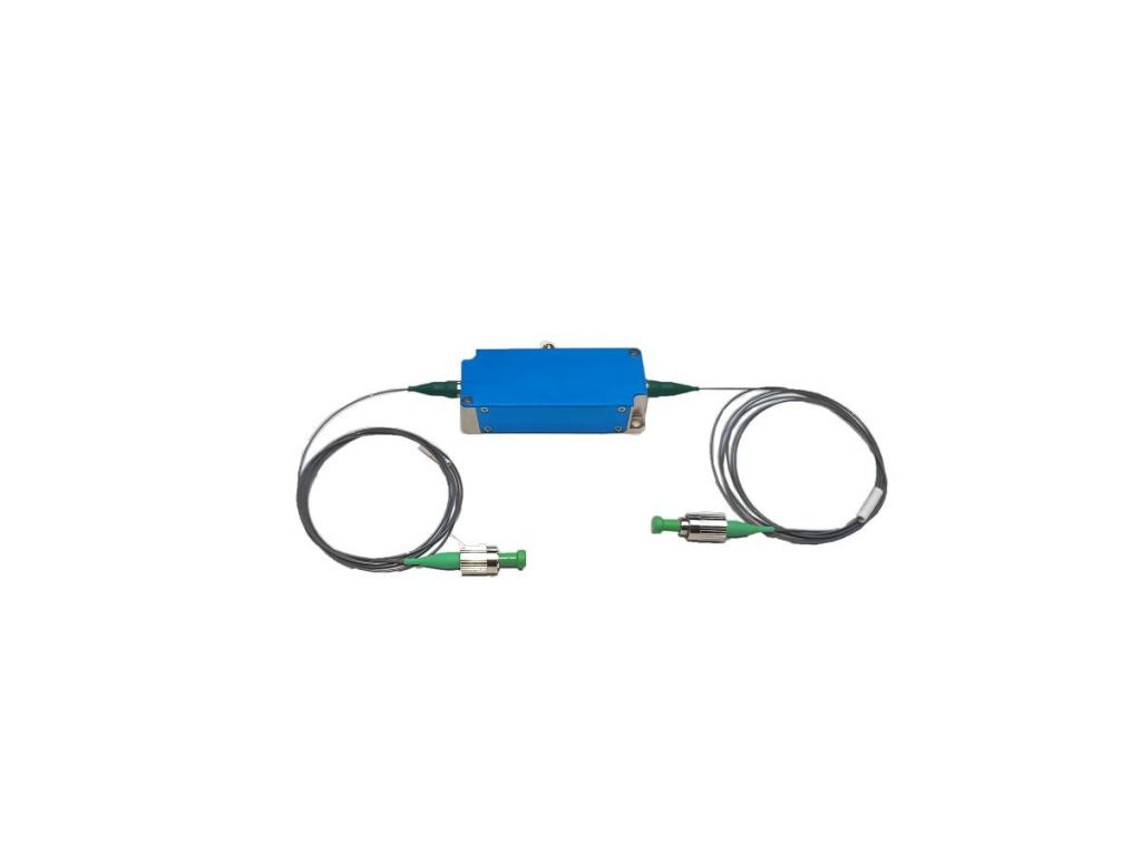
Unlike the above three types of drivers, RF signal amplifiers are drivers that amplify input bandwidth RF signals. When in use, in addition to the need to input modulation signals and power supply signals, an external RF signal is also required. The signal waveform is a sine wave or square wave, and the amplitude and frequency of the signal are determined according to the needs. As shown in the figure:

It should be clarified that regardless of the type of driver used in conjunction with AOM, the frequency of the output light relative to the input light varies, and the frequency shift varies depending on the model.
The table shows the changes in the state of the output light after using different drivers.
| Item | Input optical parameter | Output optical parameter | ||
| frequency | state | frequency | state | |
| Frequency shift driver | f=c/λ | Continuous light | f+f0 | Continuous light |
| Digital modulation driver | f=c/λ | Continuous light | f+f0 | Pulse type output (Used as an optical switch) |
| Analog modulation driver | f=c/λ | Continuous light | f+f0 | The variation trend of output light intensity is similar to the waveform of RF signal (Used for amplitude modulation) |
| Bandwidth RF amplifier | f=c/λ | Continuous light | f+f0 | Digital modulation or analog modulation |
If you are looking for optical switches, acousto-optic frequency shifters, or light intensity modulators, SMART SCI&TECH is a good choice.


