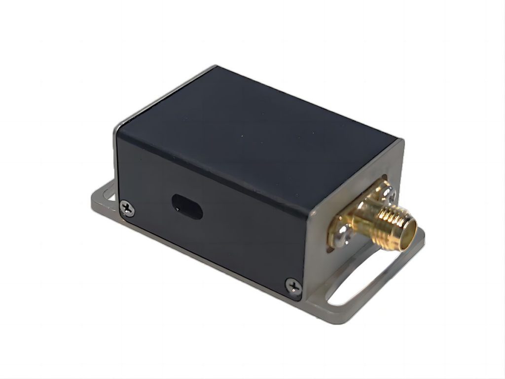
How to Integrate Acousto-Optic Q-Switches and Drivers in Your Optical Setup
Acousto-optic Q-switches are essential components in many laser systems, enabling the generation of high-energy, short-pulse laser radiation. By rapidly modulating the quality factor (Q-factor) of a laser cavity, acousto-optic Q-switches allow for precise control over the timing, duration, and energy of laser pulses. This article delves into the intricacies of integrating acousto-optic Q-switches and their corresponding drivers into optical setups, covering fundamental principles, key parameters, practical considerations, and advanced techniques.
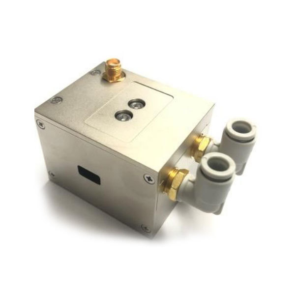
Understanding Acousto-Optic Q-Switches
What is an Acousto-Optic Q-Switch?
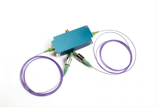
An acousto-optic Q-switch is a device that utilizes the interaction between light and sound waves to control the transmission of light within a laser cavity. It consists of an acousto-optic modulator (AOM) placed inside a laser cavity. When an RF signal is applied to a transducer attached to the crystal, it generates a high-frequency acoustic wave that propagates through the crystal. This acoustic wave creates a periodic variation in the refractive index of the crystal, forming a dynamic diffraction grating.
How Acousto-Optic Q-Switch Works
As a laser beam passes through the acousto-optic crystal, a portion of the light is diffracted by the acoustic grating. The amount of diffracted light depends on the intensity of the acoustic wave. By controlling the amplitude of the RF signal, the diffraction efficiency can be modulated, effectively switching the laser cavity on and off.
- Q-Switched Mode: When the RF signal is off, the diffraction efficiency is low, allowing most of the laser light to circulate within the cavity. As the laser medium is pumped, energy accumulates, leading to a population inversion.
- Pulse Generation: When the RF signal is switched on, the diffraction efficiency increases, diverting a significant portion of the laser light out of the cavity. This sudden loss of energy triggers a rapid release of stored energy in the form of a high-intensity laser pulse.
Key Parameters and Considerations
- Rise/Fall Time: The speed at which the Q-switch can switch the laser cavity on and off.
- Extinction Ratio: The ratio of the maximum to the minimum transmission of the Q-switch.
- Damage Threshold: The maximum optical power that the Q-switch can withstand without damage.
- Operating Wavelength Range: The range of wavelengths for which the Q-switch is designed to operate.
- Acoustic Frequency Range: The range of frequencies that the Q-switch driver can generate.
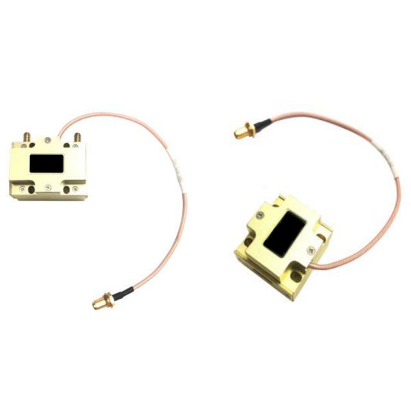
Choosing the Right Acousto-Optic Q-Switch Driver
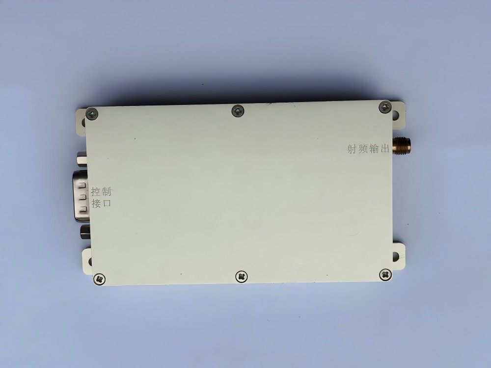
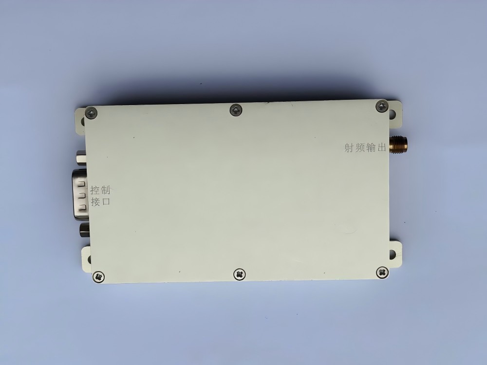
The performance of an acousto-optic Q-switch is heavily reliant on the quality of the driver that controls the RF signal. A well-designed driver ensures precise control over pulse parameters, such as repetition rate, pulse width, and energy.
Essential Features of a Q-Switch Driver
- Pulse Repetition Rate Control: The ability to adjust the frequency at which laser pulses are generated.
- Pulse Width Control: The ability to control the duration of each laser pulse.
- Amplitude Modulation: The ability to modulate the amplitude of the RF signal to fine-tune the Q-switch’s performance.
- Synchronization Capabilities: The ability to synchronize the Q-switch with other components in the laser system, such as external triggers or other lasers.
Types of Q-Switch Drivers
- Analog Drivers: These drivers use analog circuits to generate the RF signal. They offer flexibility but can be more complex to design and operate.
- Digital Drivers: These drivers utilize digital signal processing (DSP) techniques to generate precise RF waveforms. They offer high precision and stability but can be more expensive.
- Microprocessor-Controlled Drivers: These drivers combine the flexibility of analog drivers with the precision of digital drivers. They allow for advanced control features, such as programmable pulse shapes and timing sequences.
Matching the Driver to the Q-Switch
To achieve optimal performance, it is crucial to match the driver’s capabilities to the specific requirements of the acousto-optic Q-switch and the laser system. Key factors to consider include:
- RF Power Requirements: The driver must be able to deliver sufficient RF power to the Q-switch to achieve the desired diffraction efficiency.
- Frequency Range: The driver’s frequency range should cover the operating frequency of the Q-switch.
- Pulse Rise/Fall Times: The driver’s rise and fall times should be compatible with the Q-switch’s switching speed.
- Synchronization Capabilities: The driver should be able to synchronize with other components in the laser system, such as external triggers or other lasers.
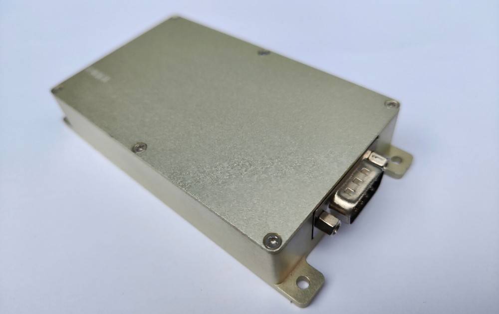
Integrating the Q-Switch and Driver into Your Optical Setup
Mechanical Integration
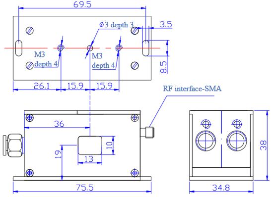
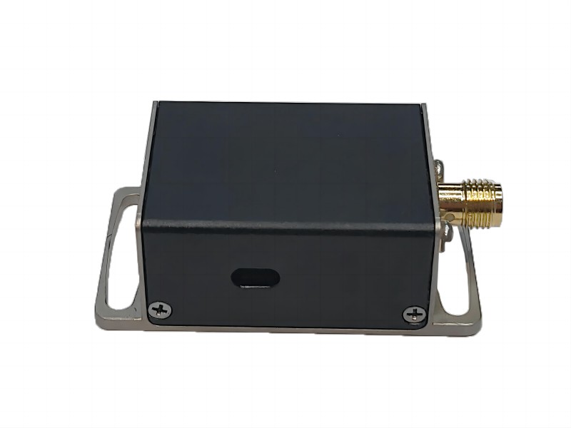
- Mounting Options: Acousto-optic Q-switches are typically mounted on optical mounts or breadboards using standard mounting holes or custom brackets.
- Alignment: Proper alignment of the Q-switch within the laser cavity is critical for optimal performance. The Q-switch should be positioned to ensure that the laser beam passes through the acousto-optic crystal at the correct angle and position.
Electrical Integration
- Power Supply Requirements: The Q-switch driver requires a stable and well-regulated power supply to ensure reliable operation.
- Signal Connections: The driver’s input and output signals should be properly connected to the control circuitry and the RF amplifier, respectively.
- Grounding: Proper grounding is essential to minimize noise and interference.
- Triggering and Synchronization: The Q-switch driver can be triggered by external signals, such as a pulse generator or a timing circuit, to synchronize the laser pulses with other events in the experiment.
Optical Integration
- Beam Propagation and Mode Matching: The laser beam should be properly mode-matched to the Q-switch’s aperture to maximize the diffraction efficiency.
- Polarization Considerations: The polarization of the laser beam should be aligned with the polarization axis of the acousto-optic crystal.
- Optical Isolation: Optical isolators can be used to prevent feedback from the Q-switch and other components, which can degrade laser performance.
Troubleshooting Common Issues
No Q-Switched Output:
- Check driver settings and connections.
- Verify Q-switch alignment and damage.
- Inspect the laser cavity for misalignment.
Poor Pulse Quality:
- Adjust driver parameters (pulse width, repetition rate).
- Optimize Q-switch alignment and drive power.
- Consider using optical isolators to reduce feedback.
Advanced Techniques and Applications
- Pulse Shaping and Timing Control: Advanced driver techniques can be used to generate custom pulse shapes, such as Gaussian, square, or triangular pulses. Precise timing control is essential for applications such as pump-probe spectroscopy and ultrafast laser systems.
- High-Power Q-Switching: For high-power applications, special considerations must be made to ensure the Q-switch’s thermal management and damage threshold.
- Ultrafast Q-Switching: By using high-frequency RF signals and ultrafast Q-switches, it is possible to generate picosecond and femtosecond laser pulses.
Overall, acousto-optic Q-switches and their drivers are powerful tools for controlling the output of laser systems. By understanding the fundamental principles, key parameters, and integration techniques, researchers and engineers can effectively incorporate these devices into their optical setups to achieve a wide range of applications.

