RF Driver Common Troubleshooting Guide
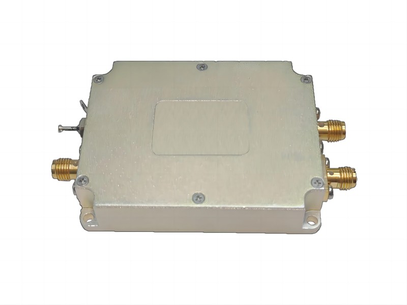
RF drivers as one of the standardized drivers are critical for amplifying and shaping signals, ensuring efficient operation in a variety of applications such as communication systems, radars, and wireless technologies. However, even the most reliable devices can experience hiccups. When your RF driver fails, understanding its behavior and using proper troubleshooting techniques is critical. Professional acousto-optic modulator driver supplier Smart provides you with the necessary knowledge to navigate the world of RF driver troubleshooting. We’ll look at the fundamentals of RF driver operation, essential troubleshooting techniques, and common issues with potential solutions. Whether you’re an experienced electronics enthusiast or just starting, this guide will help you diagnose and potentially resolve issues with your RF driver, ensuring peak performance in your projects.
Understanding RF Driver Behavior
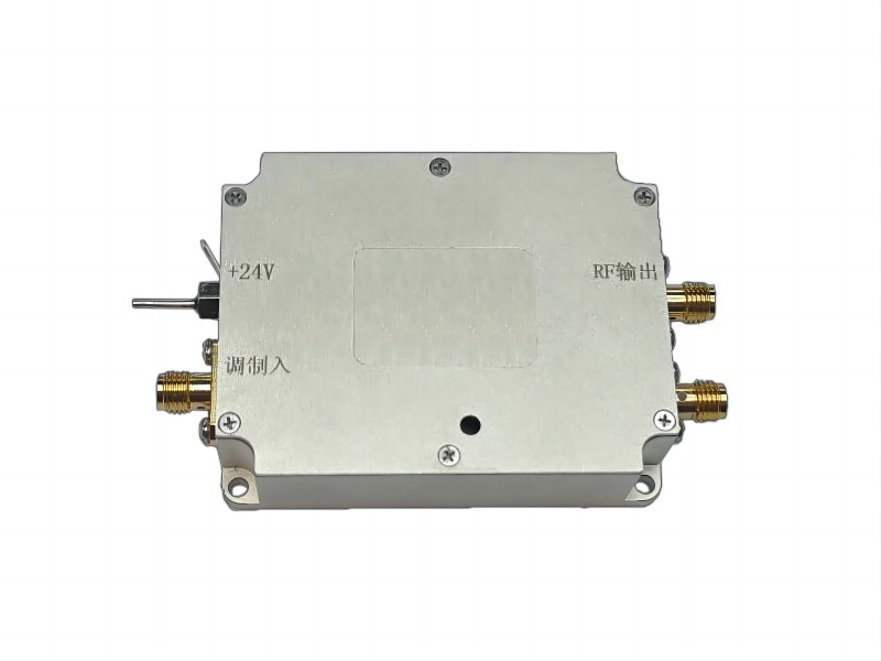
An RF driver is a critical component in many electronic systems because it acts as a link between the low-power control signal and the high-power radio frequency circuit. An RF driver amplifies and shapes the input signal to provide the power and characteristics required to drive the RF circuit. Let’s look at its core function and key specifications:
| Specification | Description | Importance |
| Gain | This parameter controls the amount of amplification provided by the driver. It is typically measured in decibels (dB) and represents the increase in signal strength after passing through the driver. | A sufficient gain ensures that the RF circuit receives enough power to perform optimally. |
| Frequency Range | This specification defines the frequencies that the driver can effectively amplify. It is critical to ensure that the driver operates within the RF circuit’s intended frequency range. | Using a driver with a compatible frequency range ensures proper signal handling for your application. |
| Output Power | This parameter represents the maximum power that the driver can deliver to the RF circuit, which is typically measured in watts (W) or milliwatts (mW). | The output power must be sufficient to operate the RF circuit without clipping or distortion. |
| Input/Output Impedance | Impedance is the opposition encountered by a signal as it travels through a circuit. The driver’s input and output impedance must match the source and RF circuit impedances, respectively. | Proper impedance matching reduces signal reflections and ensures efficient power transfer between the driver and the circuit. |
Understanding these key specifications and their impact on performance allows you to choose the best RF driver for your particular application and ensure optimal functionality within your RF circuit.
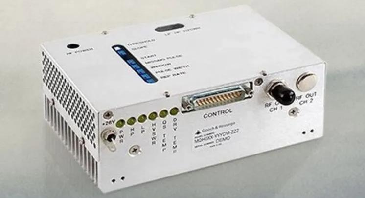
RF Driver Troubleshooting Techniques
A systematic approach is essential for effectively troubleshooting RF driver issues. Here’s a breakdown of important techniques to help you diagnose and possibly resolve problems:
1. Gathering Information
- Documenting Symptoms: The first step is to meticulously document the symptoms you’re experiencing. This includes information such as:
- Output Signal Issues: Is there no output signal at all? Is the output signal distorted or weaker than expected?
- Overheating: Is the RF driver noticeably hot to the touch?
- Other Observations: Are there any unusual noises, burning smells, or visual flickering of LEDs associated with the driver?
Recording these details provides valuable clues for pinpointing the root cause of the problem.
- Noting Changes: Consider any recent changes made to the circuit or operating environment. Did you introduce any new components? Change the power supply configuration. Understanding these changes aids in identifying possible causes of the malfunction.
2. Visual Inspection
- Physical Damage: Carefully inspect the RF driver for any signs of physical damage. Look for:
- Burnt components: Discoloration or charring on the RF driver or surrounding components may indicate overheating and component failure.
- Loose connections: Visually inspect for any loose solder joints, frayed wires, or damaged connectors. A loose connection may disrupt the signal path or power delivery.
Remember to power down the circuit before any physical inspection.
- Ventilation and Temperature: Ensure that the RF driver is properly ventilated. Inadequate airflow can cause overheating and malfunction. If possible, use a non-contact infrared thermometer to ensure the component temperature is within the recommended operating range specified in the datasheet.
3. Power Supply Checks
- Voltage Verification: Using a multimeter, measure the power supply voltage levels that reach the RF driver. Compare these measurements to the voltage specifications listed on the datasheet. Deviations from the recommended voltage can result in a variety of issues, including insufficient power delivery, erratic behavior, and even component damage.
Double-check the power supply connections to ensure they are secure. If the voltage readings are consistently incorrect, you may need to investigate the power supply itself.
4. Signal Tracing (Optional)
- Monitoring Signal Flow: For more complex troubleshooting, signal tracing can be an effective tool. This entails using an oscilloscope to monitor the signal waveform at various points in the circuit, beginning with the input to the RF driver and working toward the output.
Analyzing the signal characteristics at each stage allows you to determine where the distortion or loss is occurring. This helps determine whether the problem is with the RF driver or elsewhere in the circuit.
5. Datasheet Reference
- Troubleshooting Guidance: The RF driver’s datasheet is an excellent resource for troubleshooting. It typically includes a troubleshooting section with information on common problems and potential solutions. This section may also include specific steps to diagnose problems based on observed symptoms.
- Recommended Operating Conditions: The datasheet contains critical information about the RF driver’s recommended operating conditions, including voltage range, input/output signal levels, and temperature limits. Verifying that your circuit configuration meets these requirements can aid in identifying potential causes of malfunction.
Consulting the datasheet can provide you with valuable insights and manufacturer-recommended solutions to the specific problem you’re experiencing.
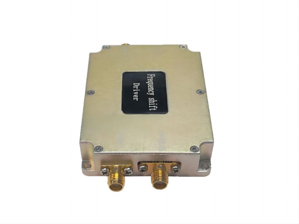
Common Problems and Solutions
Diagnosing and resolving problems with your RF driver requires a systematic approach. Here, we delve into three common problems, exploring potential causes and solutions.
| Problems | Potential Causes | Solutions |
| Low Output Power | Improper Input Signal Level: If the driver’s input signal level is too low, it may lack the necessary “oomph” to amplify it to the desired output power. Insufficient Power Supply Voltage: The RF driver requires a specific voltage range to operate properly. If the power supply voltage falls below the minimum requirement, the driver may be unable to deliver full output power. Faulty Driver Component: Internal component failure within the RF driver can also cause a decrease in output power. | Adjust Input Signal Level: If possible, consult the datasheet and set the input signal level to match the recommended range for peak driver performance. Verify Power Supply Voltage: Use a multimeter to measure the power supply voltage that reaches the driver. If it falls below the minimum specified in the datasheet, address the power supply problem or adjust the power supply settings to provide the required voltage. Consider Component Replacement: If the solutions listed above do not solve the problem, a faulty component within the driver could be the culprit. Replacing the RF driver may be necessary, but make sure you select a replacement with compatible specifications. |
| Distorted Output Signal | Overloading the Driver: Feeding the driver an input signal that exceeds the recommended level can cause clipping and distortion in the output signal.Improper Impedance Matching: Impedance mismatch between the driver’s input/output impedance and the source/RF circuit impedance can result in signal reflection and distortion.Component Malfunction: Similar to low output power, internal component failure within the RF driver can distort the output signal. | Reduce Input Signal Level: If the input signal is too strong, reduce it to within the driver’s recommended range to avoid clipping and distortion.Adjust Impedance Matching Networks: Test the impedance matching network between the driver and the source/RF circuit. You may need to change component values within the network to achieve proper impedance matching and reduce signal reflections.Consider Component Replacement: If adjusting the input signal level and impedance matching does not solve the problem, a faulty component within the driver could be causing the distortion. Replacing the RF driver may be necessary. |
| Overheating | Insufficient Ventilation: Restricted airflow around the RF driver can trap heat, causing it to overheat. Exceeding Power Rating: If the RF driver is operating at or near its maximum power rating for extended periods, it can generate excessive heat and potentially overheat. Faulty Heat Sink: The heat sink attached to the RF driver is crucial for dissipating heat. A malfunctioning or improperly mounted heat sink can lead to overheating. | Improve Ventilation: Maintain proper airflow around the RF driver. This could include using a fan or placing the circuit board in a well-ventilated enclosure. Reduce Power Dissipation: If possible, look for ways to reduce the RF driver’s power dissipation. This could include decreasing the input signal level or changing the operating mode (if applicable). Ensure Proper Heat Sink Operation: Check that the heat sink is securely mounted to the RF driver and has good thermal contact. Remove any dust or debris that has accumulated on the heat sink fins, which could impede heat dissipation. If the heat sink is damaged, consider replacing it with an appropriate one. |
These are generic troubleshooting steps. Always consult the datasheet for the specific RF driver for detailed information on recommended operating conditions and troubleshooting advice.
Conclusion
Understanding the core function of RF drivers and mastering basic troubleshooting techniques will allow you to transition from a passive observer to an active problem solver in RF circuits. This guide will teach you how to systematically diagnose issues such as low output power, signal distortion, and overheating. Remember, the datasheet is your best friend; it contains invaluable information about your specific RF driver and can provide targeted solutions. Never hesitate to seek the assistance of a qualified electronics technician when dealing with complex problems. With the information provided here, you’ll be well on your way to overcoming RF driver challenges and ensuring that your electronic projects run smoothly and efficiently.

